Posts

Showing posts with the label RPi

Motioneyeos.

Image
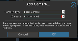
Normally I am not fond of canned software, but this one might be an exception. Motioneyeos is a raspberry pi implementation for the program Motion. Motion is software to control video capture devices. All control is done via the web. For purposes of this project we used an original raspberry pi. ( https://github.com/ccrisan/motioneyeos/releases ). There are several releases depending on the unit you have. First I tried a logitech usb camera clone. The system recognized it immediately. Not like a certain other operating system where you have to load the drivers for almost everything. Then we added an ipcamera (network ready). After adding the network camera file, it worked just like you would expect. The documentation for the camera did not have the description of the file. Fortunately the Motion software site did have that information.  ( http://www.lavrsen.dk/foswiki/bin/view/Motion/WorkingDevices ) Again no additional drivers were required. Actual picture is muc...

Raspberry pi zero.

Image
Instead of getting the rpi zero w, I will just add a usb female to my existing pi for the time being.Have lots of leftover cables for the cause.. Can always plug in a wifi or bluetooth module.   Various notes: Simplest configuration to connect to an unsecured wireless router knowing it;s essid: #linux auto lo iface lo inet loopback auto eth0 iface eth0 inet dhcp allow-hotplug wlan0 auto wlan0 iface wlan0 inet dhcp wireless-essid router-essid  Improvisational solder less header pin for the rpi zero Original pi zero fully decked out. with bluetooth, wired m and wireless. Basic setup ----------------- install jessie os do updates install vim mc Wifi ------ Check Ethernet & Wifi Before continuing make sure the Ethernet cable is connected in and you can ping out from the Pi: ping 8.8.8.8 You will also want to set up your WiFi dongle. runsudo shutdown -h now and then plug in the WiFi module when the Pi is off so you don't ca...

Another way to use audacity.

Image
Just an idea or two, My brother is an awesome guitar player and he said I could download the audio of him playing. Export files as .mp3 and then move them to the server.

Five volt adapter.

Image
If you have a bunch of old +5v powerblocks with barrel connectors, then you may think they are worthless. Not so you can now get adapters to keep using the old powerblocks with your Raspberry Pi. With the adapter, you can still use the power block as you always have and no soldering required. You could also adapt an old computer power supply. Dangerous!! Wrongly set up it could KILL you Do not do this without expert help. Every power supply is different so you will have to tget the pinout for your power supply to be used. Do not do anything while the splly is plugged in on or off!!!!  Suggestions: User your favorite search engine. AT: ATX: Polarity matters:

PiFM sorta

Image
Wanted to be able to send music to speakers outside the house say for a barbecue or whatever. Could use Blue tooth among other things, but I wanted something more secure and easier to generally implement. PiFM seemed to be an answer . With a RPi you can send an old fashion radio signal to a radio and the radio will play what is sent it. All you need is an up to date Raspian install on a Raspberry Pi with internet access. I used the original  Raspberry pi for this project. I will probably set one up with the RPi zero. (Note: check you local laws to see if this is allowed.) Also you need to have experience using you RPi remotely. Antenna needs to be at least 7-14 inches long. You need to log into your Rpi command line. All this can be done easily. First thing is to get some software from the software repo for doing software development. Don't worry it will not hurt too bad. Update the system: $ sudo apt-get update $ sudo apt-get upgrade -y $ sudo apt-get dist-update -y...

RPi gadget hint.

Suggested for the /etc/network/interfaces file Existing rpi configuration: allow - hotplug usb0 iface usb0 inet static address 192.168 . 7.2 netmask 255.255 . 255.0 network 192.168 . 7.0 broadcast 192.168 . 7.255 gateway 192.168 . 7.1 Recommended change: auto usb0 iface usb0 inet static address 192.168 . 7.2 netmask 255.255 . 255.0 network 192.168 . 7.0 broadcast 192.168 . 7.255 gateway 192.168 . 7.1 Existing host machine c onfiguration: allow - hotplug usb0 iface usb0 inet static address 192.168 . 7.2 netmask 255.255 . 255.0 network 192.168 . 7.0 broadcast 192.168 . 7.255 gateway 192.168 . 7.1   Recommended change:   auto usb0 iface usb0 inet static address 192.168 . 7.1 netmask 255.255 . 255.0 network 192.168 . 7.0 broadcast 192.168 . 7.255 gateway 192.168 . 7.1

Starting RPi gpio output.

Image
 Here is a little project I just started on. Have done a lot of work with a legacy Pc port. In fact, a lot of interfacing to different devices have been documented in my blogs. One thing you have to be careful of is that the pinouts vary between the different Raspberry Pi models. Here is the wiring diagram for the original RPi and for the RPi zero. An article recommends 470 ohm resisters. Not a fan of python, but there is a lot code that can be used. Python code. (railroad track warning lights.) -------------------- #Import libraries import RPi.GPIO AS GPIO import time #set gpio numbering mode and defind pins GPIO.setwarnings(False) GPIO.setmode)GPIO.BOARD) GPIO.setup(7, GPIO.OUT) GPIO.setup(11, GPIO.OUT #blink the leds for x in range(0.10):     GPIO output(7, True)     GPIO output(11, False)     time.sleep(.5)     GPIO output(7, False)     GPIO output(11, True)  ...

Rpi zero composite out.

Image
So you've got your Pi Zero, but you don't have an HDMI monitor! The Pi Zero has a composite video out port which is very easy to access, and we're going to show you how!  You'll need a few bits and pieces, including a soldering iron to solder some headers on: We're going to be soldering two pin headers onto the Pi Zero, circled in red and labeled TV in the picture below So, go ahead an solder your pin headers on! You can of course solder wires directly to the board if you'd like, but headers are neater (and their connection subsequently removable). Now get your RCA connector, and plug the two male ends into the two screw terminals. Again, you can use wire for this, but male pins are probably neater. Now we can plug the female end of the jumper wires into our Zero. Polarity should always be "Positive" (+) of the RCA connector, to the pin labelled "TV" on the Raspberry Pi. In this case, it is our white jumper wire. ...

Raspberry Pi resolution.

Thoughts on resolution setup. Originally 320x200 # uncomment this if your display has a black border of unused pixels visible # and your display can output without overscan #disable_overscan=1 disable_overscan=1  # uncomment to force a console size. By default it will be display's size minus # overscan. #framebuffer_width=1280 #framebuffer_height=720 framebuffer_width=1024 framebuffer_height=768 -------- config.txt As it's an embedded platform, the Raspberry Pi doesn't have a BIOS like you'd find on a conventional PC. The various system configuration parameters, which would traditionally be edited and stored using a BIOS, are stored in an optional text file named config.txt . This is read by the GPU before the ARM CPU and Linux are initialised, therefore it must be located on the first (boot) partition of your SD card, alongside bootcode.bin and start.elf . This file is normally accessible as /boot/config.txt from Linux a...

Raspberry pi zero

Image
Bought some of the Raspberry Pi Zeros for five dollars.  Was able to install the standard Raspian image on an mm card and boot up without problem. On the system I used I remotely logged into the Rpi via ssh so that I did not need a monitor. Changed the user password and shut down. For the image you will need to to use a micro sd card for the image. The raspberry website has all the details how to do that.  Used a regular sd card with a micro insert so that the usb to mmccard adapter would easily handle the image to the card. There are two micro usb ports on the board so that one is for power and the other is for a regular usb connection. They are marked on the board. On the regular usb port, I hooked up an otg cable connected to a usb ethernet adapter. Raspian saw the ethernet adapter without any problem. As for audio, you have to use the hdmi adapter, though to connect to a regular hdmi cable you will need a mini to standard adapter. So you might as well get  h...