Pwm
From Wikipedia:
Pulse-width modulation (PWM), or pulse-duration modulation (PDM), is a technique used to encode a message into a pulsing signal. It is a type of modulation. Although this modulation technique can be used to encode information for transmission, its main use is to allow the control of the power supplied to electrical devices, especially to inertial loads such as motors. In addition, PWM is one of the two principal algorithms used in photovoltaic solar battery chargers,[1] the other being MPPT.
The average value of voltage (and current) fed to the load is controlled by turning the switch between supply and load on and off at a fast rate. The longer the switch is on compared to the off periods, the higher the total power supplied to the load.
The PWM switching frequency has to be much higher than what would affect the load (the device that uses the power), which is to say that the resultant waveform perceived by the load must be as smooth as possible. Typically switching has to be done several times a minute in an electric stove, 120 Hz in a lamp dimmer, from few kilohertz (kHz) to tens of kHz for a motor drive and well into the tens or hundreds of kHz in audio amplifiers and computer power supplies.
The term duty cycle describes the proportion of 'on' time to the regular interval or 'period' of time; a low duty cycle corresponds to low power, because the power is off for most of the time. Duty cycle is expressed in percent, 100% being fully on.
The main advantage of PWM is that power loss in the switching devices is very low. When a switch is off there is practically no current, and when it is on and power is being transferred to the load, there is almost no voltage drop across the switch. Power loss, being the product of voltage and current, is thus in both cases close to zero. PWM also works well with digital controls, which, because of their on/off nature, can easily set the needed duty cycle.
PWM has also been used in certain communication systems where its duty cycle has been used to convey information over a communications channel.
Most micro controllers have pwm pins on board, but you can easily generate or simulate pwm in software for systems without pwm pins. First you do not see the "1" and then you see more of it. Code compiled with freebasic fbc -lang qb [filename]
[code]
cls
for x = 1 to 1000
for y =1 to (1000 - x)
locate 1,1
?" ";
next y
for a = 1 to x
locate 1,1
?"1";
next a
next x
?
end
[/code]
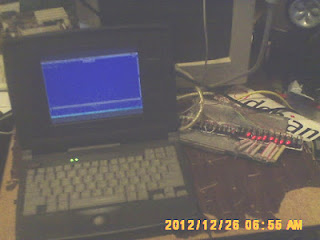
Here is another way using an actual led connected to the parallel port. Emu;ates the idea of the lights dimming and getting brighter.
out 888,0 turns all lights off
out 888,255 turns all lights on
[code]
cls
for x = 1 to 50
for y =1 to x
locate 1,1
rem ?"1";
out 888,255
for z = 1 to 500000
next z
next y
for a = 1 to 50 -x
locate 1,1
rem ?" ";
out 888,0
for z = 1 to 500000
next z
next a
next x
out 888,0
[/code]
or
[code]
cls
for x = 1 to 1000
for y =1 to (1000 - x)
locate 1,1
rem ?" ";
out 888, 0
next y
for a = 1 to x
locate 1,1
rem ?"1";
out 888,255
next a
next x
out 888,0
[/code]
Of course you can do it with single led's also.


Comments
Post a Comment