Posts

Showing posts from 2016

Legacy computer home automation server

Image
Using legacy systems to do home automation when an Arduino or Raspberry Pi may not be available. They can work just as well.  Server is a Pentium III with Ubuntu and Apache2. Enabled CGI (common gateway interface). Wrote all my own scripts using html, bash, and compiled freebasic (controls the leds).    Leds are connected to the parallel port via a home made adapter cable. Most of the code and interfaces are described in previous articles.  Added the video to the home web page: Time to control real world object such as a coffeemaker. For more information: http://www.tldp.org/HOWTO/text/Coffee
Chromecast ethernet.

Image
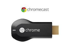
You can use ethernet with the Chromecast (1), you just need a usb ethernet adapter and then a otg y host adapter (system must be up to date). Then it should be plug and play if you have the right ethernet adapter. Tried my ethernet adapter and it did not work. Went to Frys who had the right usb to ethernet adapter. All was well till I found that the Home android app on the Nexus 7 did not seem to support ethernet. Though I did not spend anytime seeing whether it could be done. A bummer.

Five volt adapter.

Image
If you have a bunch of old +5v powerblocks with barrel connectors, then you may think they are worthless. Not so you can now get adapters to keep using the old powerblocks with your Raspberry Pi. With the adapter, you can still use the power block as you always have and no soldering required. You could also adapt an old computer power supply. Dangerous!! Wrongly set up it could KILL you Do not do this without expert help. Every power supply is different so you will have to tget the pinout for your power supply to be used. Do not do anything while the splly is plugged in on or off!!!!  Suggestions: User your favorite search engine. AT: ATX: Polarity matters:

Barebone arduino ethernet.

Image
Notice: use at your own risk. If you have an Arduino with a removable chip, then you can use that to program the chip. Otherwise there are circuits to program the standalone Arduino. See "https://www.arduino.cc/en/Tutorial/ArduinoToBreadboard" for more details".   The bare Arduino setup. You need a power source not shone. We used a 4 D size battery setup. Barebones setup before adding ethernet: Wiring:  Downloaded the latest Arduino and Ethercard software. Loaded both of them on the computer. Imported code for a simple web server. // Present a "Will be back soon web page", as stand-in webserver. // 2011-01-30 <jc@wippler.nl> http://opensource.org/licenses/mit-license.php #include <EtherCard.h> #define STATIC 0  // set to 1 to disable DHCP (adjust myip/gwip values below) #if STATIC // ethernet interface ip address static byte myip[] = { 192,168,1,200 }; // gateway ip address static byte gwip[] = { 192

Documentation is bad sometimes.

Image
Sometimes you just want to tear your hair out when the documentation of a product is WRONG. Something I ran into recently when trying to attach an enc28j60 from Hanrun to my genuine Arduino. I have used the ethernet shield on the Arduino without a hitch. So I supposed there would be no problem again... So I thought. Followed the map for hooking the two devices together as follows: VCC -   3.3V GND -    GND SCK - Pin 13 SO  - Pin 12 SI  - Pin 11 CS  - Pin  8 Downloaded the latest Arduino and Ethercard software. Loaded both of them on the computer. Imported code for a simple web server. // Present a "Will be back soon web page", as stand-in webserver. // 2011-01-30 <jc@wippler.nl> http://opensource.org/licenses/mit-license.php #include <EtherCard.h> #define STATIC 0  // set to 1 to disable DHCP (adjust myip/gwip values below) #if STATIC // ethernet interface ip address static byte myip[] = { 192,168,1,200 }; // gateway ip address static by

PiFM sorta

Image
Wanted to be able to send music to speakers outside the house say for a barbecue or whatever. Could use Blue tooth among other things, but I wanted something more secure and easier to generally implement. PiFM seemed to be an answer . With a RPi you can send an old fashion radio signal to a radio and the radio will play what is sent it. All you need is an up to date Raspian install on a Raspberry Pi with internet access. I used the original  Raspberry pi for this project. I will probably set one up with the RPi zero. (Note: check you local laws to see if this is allowed.) Also you need to have experience using you RPi remotely. Antenna needs to be at least 7-14 inches long. You need to log into your Rpi command line. All this can be done easily. First thing is to get some software from the software repo for doing software development. Don't worry it will not hurt too bad. Update the system: $ sudo apt-get update $ sudo apt-get upgrade -y $ sudo apt-get dist-update -y

Arduino conversion.

Image
Using the Arduino development boards can be cumbersome and a bit more expensive. But for simple projects, a standalone Arduino chip just just the right choice. We will convert a typical circuit for a board to a standalone chip setup. int piezoPin = 8; // Declaring Piezo Buzzer on Pin 8 int ldrPin = 0; // Declaring LDR on Analog Pin 0 int ldrValue = 0; // Reading different values from the LDR void setup() { } void loop() { // Starting the cycle functions below ldrValue = analogRead(ldrPin); // read the value from the LDR tone(piezoPin,1000); // Play a 1000Hz tone from the piezo (beep) delay(25); // wait a bit, change the delay for fast response. noTone(piezoPin); // stop the tone after 25 ms in this case delay(ldrValue); // wait the amount of milliseconds in ldrValue } // End of cycle functions      Or   // variable declaration // sensor value int value; // low sensor value calibration int low; // high sensor value calibration int high; // digit

RPi gadget hint.

Suggested for the /etc/network/interfaces file Existing rpi configuration: allow - hotplug usb0 iface usb0 inet static address 192.168 . 7.2 netmask 255.255 . 255.0 network 192.168 . 7.0 broadcast 192.168 . 7.255 gateway 192.168 . 7.1 Recommended change: auto usb0 iface usb0 inet static address 192.168 . 7.2 netmask 255.255 . 255.0 network 192.168 . 7.0 broadcast 192.168 . 7.255 gateway 192.168 . 7.1 Existing host machine c onfiguration: allow - hotplug usb0 iface usb0 inet static address 192.168 . 7.2 netmask 255.255 . 255.0 network 192.168 . 7.0 broadcast 192.168 . 7.255 gateway 192.168 . 7.1   Recommended change:   auto usb0 iface usb0 inet static address 192.168 . 7.1 netmask 255.255 . 255.0 network 192.168 . 7.0 broadcast 192.168 . 7.255 gateway 192.168 . 7.1

Starting RPi gpio output.

Image
 Here is a little project I just started on. Have done a lot of work with a legacy Pc port. In fact, a lot of interfacing to different devices have been documented in my blogs. One thing you have to be careful of is that the pinouts vary between the different Raspberry Pi models. Here is the wiring diagram for the original RPi and for the RPi zero. An article recommends 470 ohm resisters. Not a fan of python, but there is a lot code that can be used. Python code. (railroad track warning lights.) -------------------- #Import libraries import RPi.GPIO AS GPIO import time #set gpio numbering mode and defind pins GPIO.setwarnings(False) GPIO.setmode)GPIO.BOARD) GPIO.setup(7, GPIO.OUT) GPIO.setup(11, GPIO.OUT #blink the leds for x in range(0.10):     GPIO output(7, True)     GPIO output(11, False)     time.sleep(.5)     GPIO output(7, False)     GPIO output(11, True)     time.sleep(.5) # cleanup the gpio pins before ending GPIO output(11, False) GP

Rpi zero composite out.

Image
So you've got your Pi Zero, but you don't have an HDMI monitor! The Pi Zero has a composite video out port which is very easy to access, and we're going to show you how!  You'll need a few bits and pieces, including a soldering iron to solder some headers on: We're going to be soldering two pin headers onto the Pi Zero, circled in red and labeled TV in the picture below So, go ahead an solder your pin headers on! You can of course solder wires directly to the board if you'd like, but headers are neater (and their connection subsequently removable). Now get your RCA connector, and plug the two male ends into the two screw terminals. Again, you can use wire for this, but male pins are probably neater. Now we can plug the female end of the jumper wires into our Zero. Polarity should always be "Positive" (+) of the RCA connector, to the pin labelled "TV" on the Raspberry Pi. In this case, it is our white jumper wire.

Raspberry Pi resolution.

Thoughts on resolution setup. Originally 320x200 # uncomment this if your display has a black border of unused pixels visible # and your display can output without overscan #disable_overscan=1 disable_overscan=1  # uncomment to force a console size. By default it will be display's size minus # overscan. #framebuffer_width=1280 #framebuffer_height=720 framebuffer_width=1024 framebuffer_height=768 -------- config.txt As it's an embedded platform, the Raspberry Pi doesn't have a BIOS like you'd find on a conventional PC. The various system configuration parameters, which would traditionally be edited and stored using a BIOS, are stored in an optional text file named config.txt . This is read by the GPU before the ARM CPU and Linux are initialised, therefore it must be located on the first (boot) partition of your SD card, alongside bootcode.bin and start.elf . This file is normally accessible as /boot/config.txt from Linux a

Slack pxeboot floppy install.

Image
Caveat: Use at your own risk. Though I use several versions of linux, I like to use Slackware on really old systems.  Generally those systems do not have cdrom and in some cases no usb. Slackare is so versatile that you can boot from just a floppy to install slackware via gpxe from the internet,  I did an install that way with 14.1 on a p1. Now to try this with slackware 14.2.  So far so good. You can do this on other versions of linux. To me one of the most amazing things is to install linux from the internet instead of using local media. Generally if you wanted to do an install of linux, from the net, you would need a dhcp server and an tftp server with special settings. Gpxe gets around all those limitations. Quite often I will start a internet based install from a local web server. Now that the internet is slightly more dependable we can do an install from the host linux distribution sites. Today I will show you how to do it with Slackware 14.2.  More Information at ether