Posts

Showing posts from June, 2015

Walking calculator.

Image
This may not work with all calc u lators. Here is an interesting way to count footsteps and estimate how far you have walked.You need a cheap calculator, some foam or sponge, glue, foil, cellophane tape, and 2 long wires. Then you will want to make a switch. To do that, drill or punch a hole in the sponge for the to the bottom.  Glue the foil to the top and bottom of the sponge.  The two foil pieces should not be touching. Connect the wires separately to each foiled surface. Open up the calculator and connect each of the other wire ends to the top and bottom contacts of the "equals" aka = button. Put a piece of cellophane tape between the contract so that they do not connect. Close the calculator and make sure everything works normally. you would have to press the switch together for the = sign to work.  Attach the switch to the bottom of the shoe. Now enter "1 + 1" into the calculator. Start waking and you will see the count begin to rise as y...

Using your original xbox remote and sensor.

Image
Try this at your own risk. From the kodi wiki: Follow this simple procedure: Open the receiver's plastic case using a small screw driver. Carefully pry around the case. Solder the wire to the receiver using the picture below Note: This might damage the casing of the dongle. 1 Color Coded Pinout If you're using a standard USB cable you should just be able to match the colors and solder away, but to be sure check your cable with a continuity tester according to the USB spec provided here .  Red = Positive Power (+5V DC) White = Data - Green = Data + Yellow = Unused Black = Ground (0V DC)   Normal usb connections: Pin Name Cable color Description 1 VCC Red +5 VDC 2 D- White Data - 3 D+ Green Data + 4 GND Black Ground   2 Lirc Config /etc/lirc/hardware.conf : #Chosen Remote Control REMOTE="None" REMOTE_MODULES="lir...

From Hackaday: Single chip usb temperature sensor.

Image
Have not tested this, so try at your own risk. From Hackaday ( http://hackaday.io/project/6258 ) Single chip  usb temperature sensor. Description I  (the Hackaday author) created this project because I wanted to learn about PIC microcontrollers and the USB protocol. I also wanted to see how simple I could make a USB device. I've gotten it down to two components: a PIC16F1455 microcontroller and the USB connector. The microcontroller acts as a USB serial device and will send the temperature as an ASCII string once per second. Details The PIC16F1455 is a relatively new microcontroller that can do USB without an external crystal. It also has internal pull-up resistors for the USB data lines. These things mean no extra hardware is necessary for USB communication. I needed something useful to send over USB and I noticed that the PIC16F1455 has a...

Ancestry.

Image

Return on investment aka ROI.

Image
Return on investment.What is that exactly? Theory is that as you make an investment, the cost for you will diminish and you have a larger share of the profits to use. The longer you can use an investment, it is like putting dollars in the bank, because you do not have additional investment costs. When was the last time you heard a major software company mention their ROI for you? They just want to keep taxing you incrementally. . Which of the two do you think you will get the best return n investment from? Eventually you will want to upgrade equipment, but if you can delay those costs, are you not in a better position to bargain?

Refresment zone

Image

Relief zone.

Image

Spoiled brats.

Image

Baby steps to home automation, part 2

Image
When it comes to home automation, you could use any number of systems such as a off the shelf turnkey solution such as Insteon.Check with your hardware store for more details. You could build it yourself. Unless you are experienced at it, I would let a professional do it, if for no other reason of safety to yourself and others.  If you do do it yourself, you will have to write the software to make it all happen. Though most of it may not be that hard, it can be daunting to the inexperienced. Again get a professional and a mentor. Also any drawings in this article are oversimplified and not to be used in actual systems.  What to do first? You want to make a plan of what you want to do including any budget considerations. (What is it going to cost?) Home Automation – Requirements Checklist Functional Areas:     Controls         Standalone time-based controllers         Re...

Pwm

Image
From Wikipedia: Pulse-width modulation ( PWM ), or pulse-duration modulation ( PDM ), is a technique used to encode a message into a pulsing signal . It is a type of modulation . Although this modulation technique can be used to encode information for transmission, its main use is to allow the control of the power supplied to electrical devices, especially to inertial loads such as motors. In addition, PWM is one of the two principal algorithms used in photovoltaic solar battery chargers, [1] the other being MPPT . The average value of voltage (and current ) fed to the load is controlled by turning the switch between supply and load on and off at a fast rate. The longer the switch is on compared to the off periods, the higher the total power supplied to the load. The PWM switching frequency has to be much higher than what would affect the load (the device that uses the power), which is to say that the resultant waveform perceived by the load must be as smooth as ...

The arduino web server.

Image
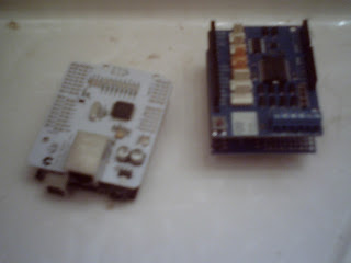
      Minimal to use the Arduino as a web server and that is already in a sketch that you can use. You need to edit the code so it will work in your network.   [code] #include <SPI.h> #include <Ethernet.h> /******************** ETHERNET SETTINGS ********************/ byte mac[] = { 0x90, 0xA2, 0xDA, 0x0D, 0x85, 0xD9 }; //physical mac address byte ip[] = { 192, 168, 0, 112 }; // ip in lan byte subnet[] = { 255, 255, 255, 0 }; //subnet mask byte gateway[] = { 192, 168, 0, 1 }; // default gateway EthernetServer server(80); //server port void setup() { Ethernet.begin(mac,ip,gateway,subnet); // initialize Ethernet device server.begin(); // start to listen for clients pinMode(8, INPUT); // input pin for switch } void loop() { EthernetClient client = server.available(); // look for the client /* a place for the code*/ dela...

PC oscilloscope.

Image
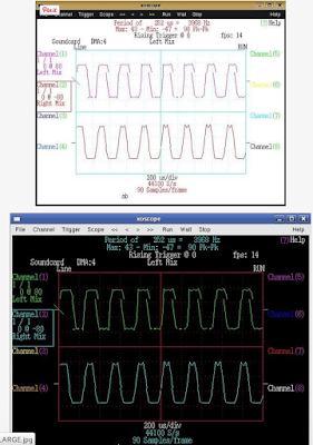
PC oscilloscope or how to save yourself hundreds of dollars before you buy an oscilloscope. Sometimes when I build simple ttl (Transistor–transistor logic) circuits I like to see the results of the output. An example would be the pwm (Pulse-width modulation) that might control a robot motor. I do not have the money to buy an oscilloscope. so I am using this project to fulfill those needs. Note I am assuming you know how to use this set up. If you are not sure, please get a professional to help. If you are unfamiliar with electronics do not do this without help of a professional. Improper probes could destroy your computer, what is connected to your computer, and as well as not be safe. Step 1: Input probe. You may want to build this input probe from the first diagram. http://nte01.nteinc.com/nte/NTExRefSemiProd.nsf/$$Search is a good place to go to get equivalent part numbers.  Also included are other...

Several RPi;s.

Image
Ideas on holding several Raspberry Pi's together, or put them into individually stackable cases

Just a new package.

Image

What they do not tell you.

Image

Not MSWindows 10 ready,

Image
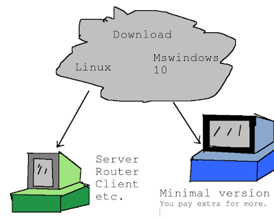
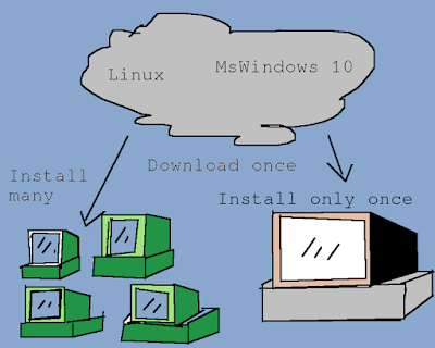
Guess I am old fashioned, but a computer is not a real computer if it does not have slots.This Pentium 1 is not MSWindows 10 ready. Who cares Slackware 14,1 runs just fine. Some computers may never die.

Free as in speech.

Image

We don't need no stinkin license..

Image

Not for me

Image
Extend, embrace, and extinguish.

Baby steps to home automation, part 1,

Image
There are many parts to home automation but the main need is to be able to turn something on or off. Without that the rest is meaningless. Let us start with a simple light switch that you can control manually. The off position we will call zero and the on position we will call the one state. Of course the purpose of home automation is for you not to have to manually turn off or on a switch. So we can get an electronic part known as a switching transistor to do the job for us with the help of a computing device that we can program. These diagrams are way over simplified to make things simpler. We could ask the computer to turn off all the leds with a command like out 888,0 and if any leds were on, they would immediately turn off. The again, we could issue a command to turn them all on with out 888,255 Then you would want to turn them off and on individually also. Then you would either write some code or have a pre-written program to do it for you and have ...