Making led control easy.
Controlling leds can be a real challenge, unless you know how to use a bit shifter aka the 74hs595. Oversimplified here, but one you get the gist of it only the sky is the limit.
From wikipedia:(https://en.wikipedia.org/wiki/Shift_register)
In digital circuits, a shift register is a cascade of flip flops, sharing the same clock, in which the output of each flip-flop is connected to the "data" input of the next flip-flop in the chain, resulting in a circuit that shifts by one position the "bit array" stored in it, shifting in the data present at its input and shifting out the last bit in the array, at each transition of the clock input. More generally, a shift register may be multidimensional, such that its "data in" and stage outputs are themselves bit arrays: this is implemented simply by running several shift registers of the same bit-length in parallel. Shift registers can have both parallel and serial inputs and outputs. These are often configured as 'serial-in, parallel-out' (SIPO) or as 'parallel-in, serial-out' (PISO). There are also types that have both serial and parallel input and types with serial and parallel output. There are also 'bidirectional' shift registers which allow shifting in both directions: L→R or R→L. The serial input and last output of a shift register can also be connected to create a 'circular shift register'.
74HC595 serial to parallel data converter that accepts one bit at a time, but the buffers can be daisy chained to almost limitless control of outputs. When DS pulses from the PC, you see that Output 0 and Output 1 on IC chip#1, goes high. Then IC chip #1 has determined that 8 pulses have past and it is time to pulse it's Q7' output which is connected to the next IC #2 chip's DS input. When the DS input of IC #2 gets a pulse from the Q7' output of IC #1, outputs 4, 5, 6, and 7 go high on chip #2. When the PC sends a DS pulse to IC #1 again, IC #1 reads the first eight bits from ST_CP and Output 0 on IC #1 turns off but output 1 stays on because it got a pulse and so on...........
[code]
int DS_pin = 8;
int STCP_pin = 9;
int SHCP_pin = 10;
void setup()
{
pinMode(DS_pin,OUTPUT);
pinMode(STCP_pin,OUTPUT);
pinMode(SHCP_pin,OUTPUT);
writereg();
}
boolean registers[8];
void writereg()
{
digitalWrite(STCP_pin, LOW);
for (int i = 7; i>=0; i--)
{
digitalWrite(SHCP_pin, LOW);
digitalWrite(DS_pin, registers[i] );
digitalWrite(SHCP_pin, HIGH);
}
digitalWrite(STCP_pin, HIGH);
}
void loop()
{
for(int i = 0; i<8; i++)
{
registers[i] = HIGH;
delay(100);
writereg();
}
for(int i = 7; i>0; i--)
{
registers[i] = LOW;
delay(100);
writereg();
}
}[/code]
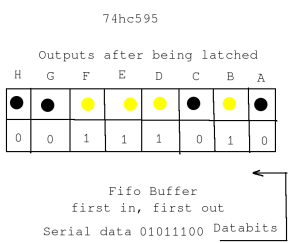
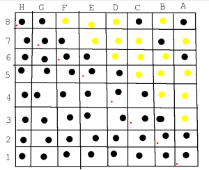
The data entering the buffer might look like this assuming all the previous data bits are zeros.
Possible Arduino setup,
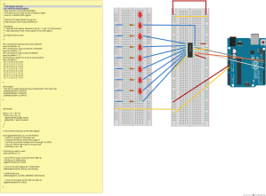

Several can be connected together with just a few control lines.

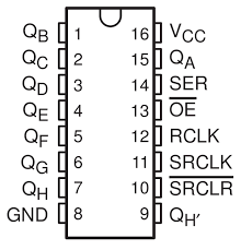
The pin-outs for the dip (dual in-line package) version.



Comments
Post a Comment